總網頁瀏覽量

2016年5月31日 星期二

更新 Motoduino WiFi Terminal (ESP8266) 韌體 步驟(Update Firmware)


刷新 Motoduino WiFi Terminal 韌體 步驟如下 :


使用材料:

1. Micro USB   x 1
2. USB TO TTL 轉接線  x 1
3. RJ114pin杜邦線  x 1
4.軟體功具 ESP DOWNLOAD TOOL V2.4 


大致上步驟:
1. 硬體接線如下圖:
黑色接 GND   黃色接 TX    綠色接 RX


2.  設定WiFi 模組為PRG 模式(燒錄韌體模式)。把UCB TO TTL接到PC,然後WiFi模組開關撥到PRG位置,如下圖


3.  開啟FLASH TOOL (ESP_DOWNLOAD_TOOL_V2.4.exe),設定如下面畫面!


4.  燒錄韌體成功畫面如下


5.  關閉 FLASH TOOL 燒錄功具, 開啟Arduino IDE Serial Monitor, 且設定如下圖!


6.  修改 baud rate 9600


7.  檢查是否修改成功,修改Serial Monitor baud rate 9600, 然後輸入 AT 命令, 如回應 OK, 表示修改成功! 接下來就可以接到Arduino 板子上使用!


前往 Motoduino 
FB: Motoduino Taiwan

2016年2月19日 星期五

AT Commands sending to ESP8266 from Arduino IDE Serial

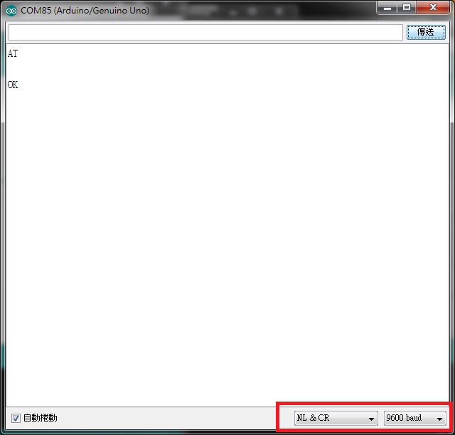
This is a Arduino sketch for AT Commands sending from Arduino Serial(TxRx) to ESP8266.
When AT commands is received by arduino, they will bypass arduino to ESP8266!


Connection examples: Motoduino WiFi Module(ESP8266) with S4A IO Board

Connections example: ESP-12


Copy and paste the following sketch to Arduino IDE! Enjoy!

///////////////////////////////////////////////////////////////////////////////////////////////////////////////
#include <SoftwareSerial.h>
SoftwareSerial esp8266(3,2);  // use pins (3,2) for software serial  S4A IO board
                                                // Rx : D3,  Tx: D2
#define DEBUG true
#define BUFFER_SIZE 512
char serBuffer[BUFFER_SIZE];
char command[128];

void setup() {

    Serial.begin(9600); // start serial communication at 9600bps
    esp8266.begin(9600); // Modify it for your esp8266 module

    Serial.println("Ready...");
}

void loop() {
  char ser_char;

    if(Serial.available()>0){
       Serial.readBytesUntil('\n', serBuffer, BUFFER_SIZE);
       int len = strlen(serBuffer);

       if(3 == len)
       {
           serBuffer[len]='\n';
           if(!strncmp(serBuffer, "AT\r\n",4))
             sendData(serBuffer, 1000, DEBUG);
       }
       else if(( len > 3)&&(serBuffer[2]=='+'))
       {
            Serial.readBytesUntil('\n', serBuffer, BUFFER_SIZE);
            len = strlen(serBuffer);
            serBuffer[len]='\n';
            //Serial.println(serBuffer);          
            sendData(serBuffer, 2000, DEBUG);
       }
          clearBuffer();
    }
}

String sendData(String command, const int timeout, boolean debug)
{
    String response = "";
   
    esp8266.print(command); // send the read character to the esp8266
    long int time = millis();
    while( (time+timeout) > millis())
    {
      while(esp8266.available())
      {      
        // The esp has data so display its output to the serial window
        char c = esp8266.read(); // read the next character.
        response+=c;
      }
    }
    if(DEBUG){
      Serial.print(response);
    }
    return response;
}

void clearBuffer(void) {
       for (int i =0;i<BUFFER_SIZE;i++ ) {
         serBuffer[i]=0;
       }
}

2016年2月5日 星期五

Motoduino WiFi Terminal Esp8266(ESP-12)


"硬"式要它更簡單!
今天要來介紹新設計的無線模組Motoduino WiFi Terminal(下圖), 此模組主要元件為 ESP8266(ESP-12). 其實用法與原始模組ESP8266一樣! 不過在此設計就是希望接線簡單化配合Motoduino 一些模組應用更方便!


主要有兩種方式可以使用此WiFi Terminal.

一. 結合Arduino使用
   透過S4A IO/Sensor Board 的RJ11孔位可以很方便連接Arduino開發板,下圖是配合 S4A IO Board 製作遙控車(Motoduino U1 + S4A IO Board + WiFi Teminal)! 因為ESP8266可以是AP及Station Mode,所以使用上更方便! (此範例使用Software Serial方式)
通常ESP8266有時需要較大的電流安培數(約200mA),往往Arduino本身提供的5V電源不太足夠,尤其如果再加上一些感測元件上去使得板子電流耗損更大,也因此常常聽到使用者談到穩定性問題!大部分原因來自於電源穩定性(在實驗時或從ESP8266官網了解)! 所以此模組提供一個Micro USB的外部電源接頭, 當Arduino提供電流不足給WiFi Terminal時可以利用外部電源! 此Terminal有提供開關可以電源切換!


Youtube 影片!


二. WiFi Terminal 單獨運行(如下圖)!
ESP8266本來就可以獨立運行(Standalone mode), 此WiFi Terminal模組可以利用RJ11接頭接上USB-Serial 傳輸線即可以對WiFi Terminal作programming! (如下圖).


如果只是作個單一控制應用, 也可以利用RJ11接頭接上Motoduino一些Terminal如(Led, Relay, button, 等模組), 如下圖!

Youtube 影片!


如果有更複雜的應用,也可以把兩邊擴充的腳位焊上排針插在麵包板上延伸利用! 另外對Arduino 開發者來說, ESP8266也提供Library給Arduino 使用者, 透過簡單API及範例可以縮短開發時程!


    http://www.motoduino.com