底下說明如何製作一台循線自走車,將沿著地上黑色膠帶往前行駛,Arduino程式撰寫非常簡單,此次利用市場最便宜的紅外線循跡感測元件(IR Tracker Sensor)來製作及Motoduino一塊板子即可以簡單做到,請參考一下做法。
一. 使用材料 : (材料購買網站)
1. Motoduino 或 Arduino + 馬達驅動板
2. 紅外線循跡感測器 (IR Tracker Sensor)
3. 9V電池一顆 及 電池釦線
4. USB傳輸線 (下載程式用)
5. 小車體套件包


圖一
安裝過程 (step by step):
Step 1:
圖一是所有組裝材料及工具,首先可以先把車子底盤兩面的土黃色貼紙撕下,需要花點時間撕下因為黏膠很強,如圖二,或不撕保持貼紙在上面也可以。

圖二
Step 2:
利用螺絲及馬達固定鐵片把馬達固定在車子底盤上,如圖三及圖四。

圖三

圖四
Step 3:
測速馬盤可以不裝上馬達轉軸上面,如要安裝上去要特別注意不要推的太進去,容易卡到馬達固定鐵片邊緣,圖三的測速馬盤就推太進去且利用四條馬達電線(兩黑兩紅)直接接上馬達或用焊接方式也可以。
Step 4:
萬向輪的固定比較麻煩一點,利用銅柱螺絲鎖在底盤上,固定方式請參考圖五及圖六。

圖五

圖六
Step 5:
固定IR Tracker Sensor於自走車平台下方,且利用塑膠柱螺絲鎖在前方底盤上,固定方式請參考圖七。連接 6 PIN 排線於Sensor上

 圖七
圖七
 圖八
圖八
 圖九
圖九

Arduino 程式 (Sketch):
程式說明:

/////////////////////////////////////////////
影片觀賞: http://www.youtube.com/watch?v=sTala_3r8mA&list=UU6aKpj71jLKYABYLr3Wbpuw&index=13
參考資料網站:
http://motoduino.com
http://sinocgtchen.blogspot.com


Step 6:
連接 6 PIN 排線於Sensor上,接法如圖八及圖九(實際上只接5 pin)。
Vcc --> 5V, GND-->GND, L -->D9, C-->D10, R-->D11。
如果是配合新版 Motoduino U1 則
Vcc --> 5V, GND-->GND, L -->D9, C-->D8, R-->D7
Vcc --> 5V, GND-->GND, L -->D9, C-->D10, R-->D11。
如果是配合新版 Motoduino U1 則
Vcc --> 5V, GND-->GND, L -->D9, C-->D8, R-->D7


Step 7:
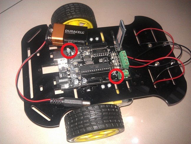
完成圖如圖十。有些細節組裝可以參考我其它文章。


圖十

Arduino 程式 (Sketch):
程式說明:

/////////////////////////////////////////////
///三路紅外線感測器與Motoduino的腳位對應
// 如果是用 Motoduino 第一版 使用如下
// 如果是用 Motoduino 第一版 使用如下
//const int SLeftLeft = 9; //左感測器輸入腳
//const int SMiddle = 10; //中間感測器輸入腳
//const int SRightRight = 11; //右感測器輸入腳
// 如果是用 Motoduino U1 則使用如下
const int SLeftLeft = 9; //左感測器輸入腳
const int SMiddle = 8; //中間感測器輸入腳
const int SRightRight = 7; //右感測器輸入腳
// 馬達與motoduino的腳位對應
// 如果是用 Motoduino 第一版
// 如果是用 Motoduino 第一版
//const int Motor_E2 = 5; // 控制馬達2轉速 digital pin 5 of Arduino (PWM)
//const int Motor_E1 = 6; // 控制馬達1轉速 digital pin 6 of Arduino (PWM)
//const int Motor_M1 = 7; // 控制馬達1正反轉 digital pin 7 of Arduino
//const int Motor_M2 = 8; // 控制馬達2正反轉 digital pin 8 of Arduino
// 如果是用 Motoduino U1 則
const int Motor_E2 = 6; // 控制馬達2轉速 digital pin 6 of Arduino (PWM)
const int Motor_E1 = 5; // 控制馬達1轉速 digital pin 5 of Arduino (PWM)
const int Motor_M1 = 10; // 控制馬達1正反轉 digital pin 10 of Arduino
const int Motor_M2 = 11; // 控制馬達2正反轉 digital pin 11 of Arduino
// 感測器狀態值
byte byteSensorStatus=0;
void setup() {
//set up serial communications
Serial.begin(57600);
// 輸出入接腳初始設定
pinMode(SLeftLeft, INPUT);
pinMode(SMiddle, INPUT);
pinMode(SRightRight, INPUT);
pinMode(Motor_M1, OUTPUT); // 設定 Motor_M1為輸出腳位
pinMode(Motor_M2, OUTPUT); // 設定 Motor_M2為輸出腳位
}
//////////// 主程式 ////////
void loop(){
int nIRStatus;
//清除感測器狀態值
byteSensorStatus = 0;
// 讀取左感測器狀態值
nIRStatus = digitalRead(SLeftLeft);
if(nIRStatus == 1)
byteSensorStatus = (byteSensorStatus | (0x01 << 2));
// 讀取中間感測器狀態值
nIRStatus = digitalRead(SMiddle);
if(nIRStatus == 1)
byteSensorStatus = (byteSensorStatus | (0x01 << 1));
// 讀取右邊感測器狀態值
nIRStatus = digitalRead(SRightRight);
if(nIRStatus == 1)
byteSensorStatus = (byteSensorStatus | 0x01);
drivemotor(byteSensorStatus);
}
///////////////////////////
void drivemotor(byte nStatus)
{
switch(nStatus)
{ // 感測器 黑色:1 白色:0
case 7: // SL:1 SM:1 SR:1 //黑黑黑
motorstop(0, 0);
break;
case 6: // SL:1 SM:1 SR:0 //黑黑白
left(0, 255);
break;
case 5: // SL:1 SM:0 SR:1 //黑白黑
motorstop(0, 255);
break;
case 4: // SL:1 SM:0 SR:0 //黑白白
left(0, 255);
break;
case 3: // SL:0 SM:1 SR:1 // 白黑黑
right(0, 255);
break;
case 2: // SL:0 SM:1 SR:0 // 白黑白
forward(0, 255);
break;
case 1: // SL:0 SM:0 SR:1 // 白白黑
right(0, 255);
break;
case 0: // SL:0 SM:0 SR:0 //白白白
forward(0, 255);
}
}
void motorstop(byte flag, byte motorspeed)
{
Serial.println("停止!");
digitalWrite( Motor_E1, motorspeed);
digitalWrite( Motor_E2, motorspeed);
}
void forward(byte flag, byte motorspeed)
{
Serial.println("forward!");
digitalWrite( Motor_M1, HIGH);
digitalWrite( Motor_M2, HIGH);
analogWrite( Motor_E1, motorspeed);
analogWrite( Motor_E2, motorspeed);
}
void backward(byte flag, byte motorspeed)
{
Serial.println("backward!");
digitalWrite( Motor_M1, LOW);
digitalWrite( Motor_M2, LOW);
analogWrite( Motor_E1, motorspeed);
analogWrite( Motor_E2, motorspeed);
}
void right(byte flag, byte motorspeed)
{
Serial.println("right!");
digitalWrite( Motor_M1, HIGH);
digitalWrite( Motor_M2, HIGH);
analogWrite( Motor_E1, 0);
analogWrite( Motor_E2, motorspeed);
}
void left(byte flag, byte motorspeed)
{
Serial.println("left!");
digitalWrite( Motor_M1, HIGH);
digitalWrite( Motor_M2, HIGH);
analogWrite( Motor_E1, motorspeed);
analogWrite( Motor_E2, 0);
}
////////////////////////////////////////////////////
影片觀賞: http://www.youtube.com/watch?v=sTala_3r8mA&list=UU6aKpj71jLKYABYLr3Wbpuw&index=13
參考資料網站:
http://motoduino.com
http://sinocgtchen.blogspot.com