總網頁瀏覽量

2014年5月2日 星期五

樹莓派PIR 紅外線人體感測( Motion Detection) = PIR Sensor + MotoPiduino + Raspberry Pi

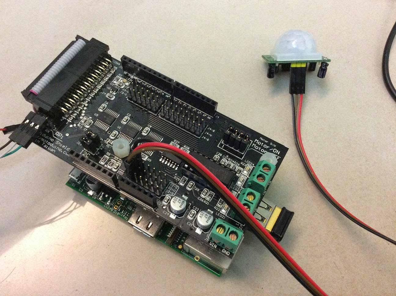
由於一般市售PIR紅外線大都是 3.3V輸出,也就是感測到移動物體時輸出 3.3V, 沒感測到時輸出 0V, 所以在MotoPiduino 板子上直接接到數位IO腳位無法判讀輸出結果,因為未達5V電壓, 此MotoPiduino是把5V電壓轉換成 3.3V樹莓派可以運作的電位. 如此我們可以利用類比IO腳位來判讀是否偵測到移動物體.

一. 使用材料:
       1. Raspberry Pi
       2. MotoPiduino
       3. PIR 紅外線感測器
       4. S4A IO Board (option)

二. 接線:
      1. 把 PIR 接到 MotoPiduino A0 位置
       或
      直接接到 S4A IO Board 的 A0 孔位

三. 接線方式如圖:


四. I2C Library 軟體下載點:
1. 下載 ADS1015 (I2C) Library : https://github.com/m3m0ry/Adafruit-Raspberry-Pi-Python-Code
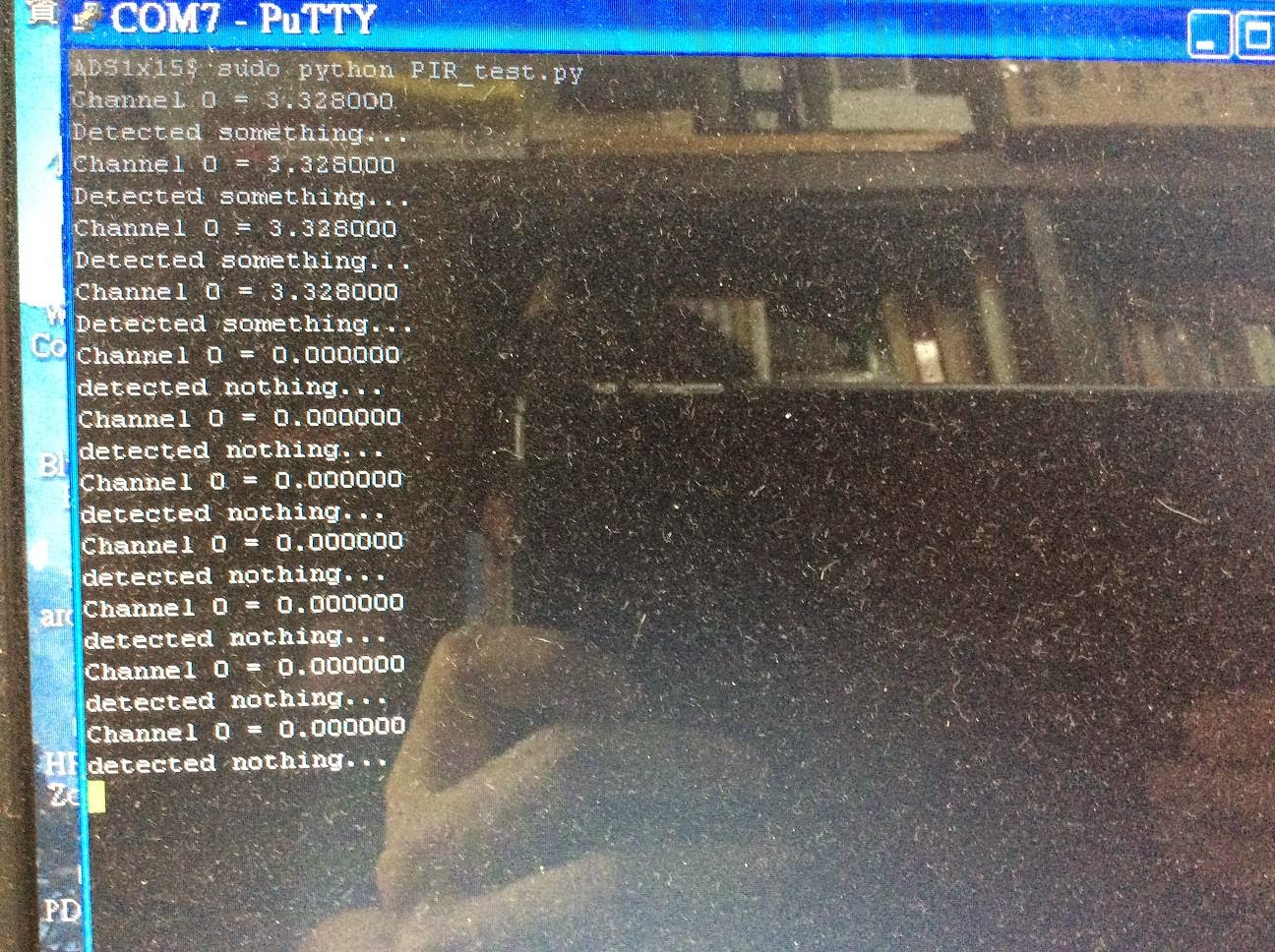
2. 編寫Python PIR 程式 my_PIR_sensor.py 如下(請該檔案建立在adafruit_ADS1x15目錄下)
import time, signal, sys
from Adafruit_ADS1x15 import ADS1x15

def signal_handler(signal, frame):
        print 'You pressed Ctrl+C!'
        sys.exit(0)
signal.signal(signal.SIGINT, signal_handler)
#print 'Press Ctrl+C to exit'

ADS1015 = 0x00  # 12-bit ADC

adc = ADS1x15(ic=ADS1015)

while True:
  # Read channel 0 in single-ended mode, +/-4.096V, 250sps
  volts = adc.readADCSingleEnded(0, 4096, 250) / 1000

  print "Channel 0 = %.6f" % (volts)
  if(volts > 3.0):
    print "Detected something..."
  else:
    print "detected nothing..."
 
  time.sleep(1)


五. 執行:
 $ sudo python my_PIR_sensor.py


Informatiom:  http://www.motoduino.com


2014年4月25日 星期五

樹莓派超音波測距 = Raspberry + Ultrasonic HC-SR04 + MotoPiduino


一. 使用材料:
       1. Raspberry Pi
       2. MotoPiduino
       3. 超音波 HC-SR04
       4. S4A IO Board (option)

二. 接線:
      1. 把 HC-SR04 接到 MotoPiduino D10 及 D11 位置, (樹莓派 GPIO8(TRIGGER) 和 GPIO10(ECHO) 位置)
       或
      直接接到 S4A IO Board 的 D10 D11孔位

三. 接線方式如圖:


4. 編寫程式:
# -----------------------

# Import required Python libraries
# -----------------------
import time
import RPi.GPIO as GPIO

# -----------------------
# Define some functions
# -----------------------

def measure():
  # This function measures a distance

  GPIO.output(GPIO_TRIGGER, True)
  time.sleep(0.00001)
  GPIO.output(GPIO_TRIGGER, False)
  start = time.time()
  
  while GPIO.input(GPIO_ECHO)==0:
    start = time.time()

  while GPIO.input(GPIO_ECHO)==1:
    stop = time.time()

  elapsed = stop-start
  distance = (elapsed * 34300)/2

  return distance

def measure_average():
  # This function takes 3 measurements and
  # returns the average.

  distance1=measure()
  time.sleep(0.1)
  distance2=measure()
  time.sleep(0.1)
  distance3=measure()
  distance = distance1 + distance2 + distance3
  distance = distance / 3
  return distance

# -----------------------
# Main Script
# -----------------------

# Use BCM GPIO references
# instead of physical pin numbers
GPIO.setmode(GPIO.BCM)

# Define GPIO to use on Pi
GPIO_TRIGGER = 8
GPIO_ECHO    = 10

print "Ultrasonic Measurement"

# Set pins as output and input
GPIO.setup(GPIO_TRIGGER,GPIO.OUT)  # Trigger
GPIO.setup(GPIO_ECHO,GPIO.IN)      # Echo

# Set trigger to False (Low)
GPIO.output(GPIO_TRIGGER, False)

try:

  while True:

    distance = measure_average()
    print "Distance : %.1f" % distance
    time.sleep(1)

except KeyboardInterrupt:
  # User pressed CTRL-C
  # Reset GPIO settings
  GPIO.cleanup()


五. 相關資訊:
相關資訊: http://motoduino.com


2014年4月17日 星期四

樹莓派LCD顯示器 = Raspberry Pi + MotoPiduino + I2C LCD 16x2

這次來說明如何把I2C LCD1602接到 Raspberry 上顯示文字及IP address, I2C LCD好處只需要佔用2支IO腳位.

一. 使用材料:
       1. Raspberry Pi
       2. MotoPiduino
       3. I2C LCD1602
       4. S4A Sensor Board (option)

二. 接線:
      1. 把 LCD1602 接到 A4 (SDA) and A5 (SCL) 位置
       或
      直接接到 S4A IO Board 的 A4A5孔位

三. 接線方式如圖:


四. I2C LCD Library 軟體下載點:
1. 建立一個目錄及下載程式: https://github.com/paulbarber/raspi-gpio
2. 檢查LCD的 I2C 位置(需事先開啟I2C功能), 此例子為0x27, 如下圖:


     3. 修改 lcd_display.py 內的LCD ADDRESS 如下圖:


     4. 編寫LCD 測試程式 lcd_i2c_test.py 如下(請將該檔案建立在剛下載的Library目錄下)


       from lcd_display import lcd
       from subprocess import *

       my_lcd = lcd()

       cmd = "ip addr show wlan0 | grep inet | awk '{print $2}' | cut -d/ -f1"

       def run_cmd(cmd):
       p = Popen(cmd, shell=True, stdout=PIPE)
       output = p.communicate()[0]
       return output

       ipaddr = run_cmd(cmd)
       ipaddrstr = 'IP:' + ipaddr 
       my_lcd.display_string("Motoduino Lab", 1)
       my_lcd.display_string(ipaddrstr, 2)


五. 執行:
 $ sudo python lcd_i2c_test.py


相關資訊: http://motoduino.com


2014年4月16日 星期三

樹莓派溫度感測 = Raspberry Pi + MotoPiduino + LM35 + S4A IO Board

利用 MotoPiduino的 ADC(Analog to Digital) 和 I2C 功能特點來製作一個溫度感測裝置.

一. 使用材料:
       1. Raspberry Pi
       2. MotoPiduino
       3. LM35 temperature Sensor
       4. S4A Sensor Board (option)

二. 接線:
      1. LM35 接在 A0 (Analog 0位置)

三. 接線方式如圖:


四. I2C Library 軟體下載點:
1. 下載 ADS1015 (I2C) Library : https://github.com/m3m0ry/Adafruit-Raspberry-Pi-Python-Code
2. 編寫Python LM35 程式 motopiduino_lm35.py 如下(請該檔案建立在adafruit_ADS1x15目錄下)
 
#!/usr/bin/python
import time, signal, sys
from Adafruit_ADS1x15 import ADS1x15

def signal_handler(signal, frame):
        print 'You pressed Ctrl+C!'
        sys.exit(0)
signal.signal(signal.SIGINT, signal_handler)
#print 'Press Ctrl+C to exit'

ADS1015 = 0x00  # 12-bit ADC

# Select the gain
gain = 6144    # +/- 6.144V
#gain = 4096  # +/- 4.096V

# Select the sample rate
sps = 250  # 250 samples per second

# Initialise the ADC using the default mode (use default I2C address)
# Set this to ADS1015 depending on the ADC you are using!
adc = ADS1x15(ic=ADS1015)

while(True):
     # Read channel 0 in single-ended mode using the settings above
     volts = adc.readADCSingleEnded(0, gain, sps)
     # 10mv per degree
     lm35_c = ((volts/ 10.0)-1.5)
     # To read channel 3 in single-ended mode, +/- 1.024V, 860 sps use:
     # volts = adc.readADCSingleEnded(3, 1024, 860)

     print "%.6f" % (lm35_c)
     time.sleep(1);


五. 執行:
 $ sudo python motopiduino_lm35.py


Informatiom:  http://motoduino.com


2014年3月15日 星期六

新開發 Arduino 感測器(Terminal)介紹

最近開發了一些Arduino感測器及周邊套件可以直接接到 Arduino S4A IO Board / S4A Sensor Board:


1. 按鈕開關:  (數位訊號)


2. 紅色 LED 輸出元件: (數位訊號) 


3. 光感測元件(光敏電阻): (類比訊號)


4. OH49E 霍爾感測器: (類比訊號)


5. DHT11 溫濕感測器 : (數位訊號)


6. DS18B20 水溫感測器: (類比訊號)


7. 微動開關 : (數位訊號)


8. PIR 人體紅外線感測器: (數位訊號)


2014年1月25日 星期六

S4A IO Board/Shield for Arduino 詳細介紹

一.簡介

    S4A IO Board/shield主要設計給ArduinoS4A初學者使用的一塊擴充板,除了支持一般杜邦接頭3 pin腳位外還可以連接10RJ11的接頭(五組數位及五組類比)感測元件(另購),如溫濕度感測器、土壤濕度感測器等。另外預留一個藍芽孔位給需要無線傳輸的使用者,可利用此無線傳輸跟Android手機或電腦溝通。此外也提供外部電源切換。此擴充板相容於Arduino Duemilanove UNOLeonado


二.   內容說明及特點:


特點:
1. 五組RJ11(6P4C電話線)數位接頭及五組類比接頭容易外接其他裝置或感測器,可以連接至少10公尺長距離的終端感測器或裝置(另購)
2. 電源紅色LED
3. 一顆 綠色LED 連接D13腳位
4. 預留一個藍芽孔位(UART)
5. Jumper可切換Vcc為內部電源(5V)或外部電源供給。


三. RJ11(6P4C電話線)接頭腳位說明
RJ11接頭中其中兩接腳為VCCGND,另外兩根接腳為IO訊號接腳,也就是說連接RJ11的感測元件可以利用此兩根IO溝通訊號,例如I2C訊號就可以利用A4A5那個孔位連接裝置。


四. 安裝藍芽模組說明


#### 請注意安裝藍芽模組腳位一定要正確對應IO Board上的藍芽預留孔位###


參考網站:  http://motoduino.com


2014年1月5日 星期日

Raspberry (樹莓派) 與 Arduino Shield 橋梁: MotoPiduino 介紹及I2C檢測

此塊MotoPiduino的功能之前大概說明過,這次說明一下IO 腳位的用途及對應Raspberry Pi的腳位.
從下圖板子可以看出有兩排腳位,此腳位剛好可以對應Arduino 腳位, 相容於Arduino UNO/Deumilanove. 也可以接兩顆DC馬達.


下圖是使用MotoPiduino時, Raspberry Pi 跟 Arduino腳位的對應. 可以看出都是Digital Pin腳位對應Raspberry Pi, 只有 A4及A5對應到Raspberry GPIO02 GPIO03, 主要是I2C 控制IO. 所以可以把以前接Arduino的 I2C 周邊接到此處(A4/A5). 


接下來說明如何 enable raspberry Pi 的 I2C 功能. 把MotoPiduino連接到Raspberry Pi後,如下圖.


sudo nano /etc/modules
#加入底下兩行
i2c-bcm2708
i2c-dev
#安裝I2C tools
sudo apt-get install python-smbus
sudo apt-get install i2c-tools
#修改raspi-blacklist.conf
sudo nano /etc/modprobe.d/raspi-blacklist.conf
#blacklist spi-bcm2708   ß 前面加個 #
#blacklist i2c-bcm2708   ß 前面加個 #
#Check連接的裝置
sudo i2cdetect -y 1


看到顯示48表示MotoPiduino上的 I2C address為 48(16進制) 處於溝通狀態. 接下來試試疊上一個Arduino Proto Shield, 在Proto Shield上有一個I2C介面重力加速度計及陀螺儀 (9DOF), Data Pin接到A4及A5. 如下圖.


在試著在command line下 sudo i2cdetect -y 1 則可以看到顯示 53數字, 表示偵測到9DOF的裝置(I2C address為 0x53).


#下一次再來說明接I2C LED 七段顯示器如何顯示數字,如下圖!