總網頁瀏覽量

2013年4月25日 星期四

(Part 1)長距離溫度感測(Temperature Sensor) = Arduino UNO + S4A Sensor Board + 7 segment LED + LM35


說明:
最近專為S4A Sensor Board 開發了幾個Sensor terminal,例如溫度感測,磁簧感測,土壤濕度感測等等,今天就拿LM35溫度感測Terminal及七段顯示器來做實驗,此Terminal設計成電話線接頭的好處就是容易接線不會接錯孔位甚至燒掉板子,另一好處是可以接長距離的電話線,此實驗利用一條10公尺電話線接LM35溫度感測terminal, 另一條約30公分的電話線接 七段顯示器, S4A sensor board疊在Arduino UNO上.

一系列的Sensor Terminal即將推出...............


使用材料:
1.Arduino UNO
2.S4A Sensor Board
3.LM35 溫度感測Terminal
4.LED七段顯示器Terminal
5.兩條6P4C或6P6C電話線.
6.9V電池一顆


執行步驟:
1.下載程式到 Arduino UNO上
2. LM35溫度感測接到 A3電話孔位
3. 七段顯示接到A4A5電話孔位
4. 接上9V電池.


Arduino Sketch:


#include <ZtLib.h>
#include <Wire.h>
#define ZTSEG8B4_ADDR  0x37

int analogPin = A3;
int readValue = 0;
float temperature = 0;
void setup()
{
   ZT.I2cInit();
   Serial.begin(9600);
}

void loop()
{
  readValue = analogRead(analogPin);  // readValue : 0~1023 (ADC 10bits)
  temperature = (readValue * 0.0049);
  temperature = temperature * 100;  //
  Serial.print("Temperature: ");
  Serial.print(temperature);
  Serial.print("C ");
  temperature = temperature * 100;  // for LED display
   ZT.Seg8b4DisplayDec(ZTSEG8B4_ADDR, temperature, DISP_AUTO, DOT_BIT2);
   delay(1000);  
}


觀賞影片:  https://www.youtube.com/watch?v=kp5WVIgRbIw

相關資訊請參考:
http://www.motoduino.com
http://sinocgtchen.blogspot.com


2013年2月21日 星期四

手機藍芽遙控車解決方案 = Motoduino (arduino) + Blutooth + android mobile


來做做android手機遙控車,不用寫任何程式也可以玩,利用Motoduino一塊板子簡單即可以簡單做到,請參考一下做法


一.  使用材料 : (材料購買網站)
1.      Motoduino 或  Arduino + 馬達驅動板
2.      TTL藍芽模組
3.      9V電池一顆 電池釦線
4.      USB傳輸線 (下載程式用)
5.      小車體套件包

圖一

安裝過程 (step by step):

 Step 1
        圖一是所有組裝材料及工具首先可以先把車子底盤兩面的土黃色貼紙撕下,需要花點時間撕下因為黏膠很強,如圖二,或不撕保持貼紙在上面也可以。

圖二


Step 2:
       利用螺絲及馬達固定鐵片把馬達固定在車子底盤上如圖三及圖四


圖三


圖四

Step 3:
         測速馬盤可以不裝上馬達轉軸上面,如要安裝上去要特別注意不要推的太進去,容易卡到馬達固定鐵片邊緣,圖三的測速馬盤就推太進去且利用四條馬達電線(兩黑兩紅)直接接上馬達或用焊接方式也可以


Step 4:
        萬向輪的固定比較麻煩一點,利用銅柱螺絲鎖在底盤上,固定方式請參考圖五及圖六


圖五


圖六


Step 5:
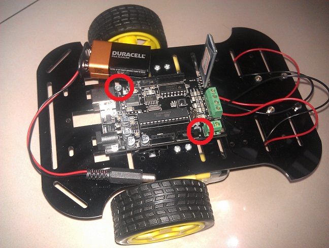
        接下來固定motoduino(arduino)板子於車子底盤上,需要兩根較長的螺絲訂定,如圖七紅色圈起來的地方。

圖七


Step 6:
        接下來利用四條電線(兩黑兩紅)直接接上馬達或用焊接方式,如圖八。注意紅黑接線的位置不要搞錯,如果接錯放心馬達不會燒掉,頂多是馬達正反轉會相反。可以在下一步驟座調適


圖八


Step 7:
         四條馬達電線接到motoduino板子上的馬達接頭 ,接線方式請參考圖九 ,以及插上藍芽模組子上,注意藍芽模組不可以接反


圖九

Step 8:
           圖十為安裝完成接上電池的狀態

圖十

Step 9:
         安裝手機APP程式到手機上。下載點請至 http://www.motoduino.com/download-twn/ 找到 Motoduino Remote Car(檔名為 mduino2.apk) ,注意手機版本要2.2以上。程式執行後畫面會出現四個按鈕,此時按下手機Menu鍵會看到一個Connect 按下Connect進入藍芽裝置搜尋畫面後按下Device Discovery開始蒐尋遙控車的藍芽裝置,後續請參考motoduino使用手冊(motoduino)


Step 10:
           一切都沒問題後就可以開始玩玩手機遙控車,按鈕遙控功能試完後記得試試一個Sensor(G-Sensor)功能,只要手機前後或左右傾斜就可以控制車子前進方向


Motoduino介紹網站: http://www.motoduino.com (source code下載處)


2012年12月17日 星期一

Arduino Interactive Shield (S4A Sensor Board)


介紹一塊新板子給初學者Arduino Interactive Shield (AIS)主要設計給ArduinoS4A初學者使用的一塊互動板,結合麥克風、按鍵開關、光源感測、滑桿式可變電阻、LED 、蜂鳴器等元件,以及四組RJ11的接頭可供外部連接其他裝置或元件,如溫濕度感測器、土壤濕度感測器等。另外預留一個藍芽孔位給需要無線傳輸的使用者。可利用此無線傳輸跟Android手機或電腦溝通。AIS板子上也預留六根數位腳位給其他需要外部電源的裝置使用,例如連接多個伺服馬達。

一.     內容說明及特點:


特點:
1. 四個RJ11接頭容易外接其他裝置(D2/D3, A3,A4,A5)
2. 一個一公分大小的按鍵開關(D2)
3. 一個蜂鳴器(D9)
4. 一個麥克風( A2)
5. 兩顆 LED 顯示,一顆為紅色(D10),一顆為綠色(D11)
6. 一個滑桿可變電阻(10K),有效行程65mm.(A0)
7. 一個光感測元件(A1)
8. 預留一個藍芽孔位(UART)
9. RJ11接頭可用電話線連接至少10米距離的感測元件


Motoduino資訊: http://motoduino.com


2012年9月20日 星期四

Arduino USB Keyboard = Arduino UNO + USB Host shield + USB keyboard

這次把做好許久的Arduino USB keyboard的做法及程式公開, 讓想學如何用USB host連接 keyboard的網友做參考(有不少網友寫mail來希望可以post出來).

DIY的材料:
1. Arduino UNO or compatible
2. USB host shield
3. USB keyboard

參考連接圖:


程式如下:  完整程式 (sketch)
------------------------------------------------------

#include <avr/pgmspace.h>

#include <avrpins.h>
#include <max3421e.h>
#include <usbhost.h>
#include <usb_ch9.h>
#include <Usb.h>
#include <usbhub.h>
#include <avr/pgmspace.h>
#include <address.h>
#include <hidboot.h>

#include <printhex.h>
#include <message.h>
#include <hexdump.h>
#include <parsetools.h>

class KbdRptParser : public KeyboardReportParser
{
        void PrintKey(uint8_t mod, uint8_t key);
        
protected:
virtual void OnKeyDown (uint8_t mod, uint8_t key);
virtual void OnKeyUp (uint8_t mod, uint8_t key);
virtual void OnKeyPressed(uint8_t key);
};

USB     Usb;
HIDBoot<HID_PROTOCOL_KEYBOARD>    Keyboard(&Usb);
uint32_t next_time;
KbdRptParser Prs;

void KbdRptParser::PrintKey(uint8_t m, uint8_t key)
{
    MODIFIERKEYS mod;
    *((uint8_t*)&mod) = m;
    Serial.print((mod.bmLeftCtrl   == 1) ? "C" : " ");
    Serial.print((mod.bmLeftShift  == 1) ? "S" : " ");
    Serial.print((mod.bmLeftAlt    == 1) ? "A" : " ");
    Serial.print((mod.bmLeftGUI    == 1) ? "G" : " ");
    
    Serial.print(" >");
    PrintHex<uint8_t>(key);
    Serial.print("< ");

    Serial.print((mod.bmRightCtrl   == 1) ? "C" : " ");
    Serial.print((mod.bmRightShift  == 1) ? "S" : " ");
    Serial.print((mod.bmRightAlt    == 1) ? "A" : " ");
    Serial.println((mod.bmRightGUI    == 1) ? "G" : " ");
};

void KbdRptParser::OnKeyDown(uint8_t mod, uint8_t key)
{
    Serial.print("DN ");
    PrintKey(mod, key);
    uint8_t c = OemToAscii(mod, key);
    
    if (c)
        OnKeyPressed(c);
}

void KbdRptParser::OnKeyUp(uint8_t mod, uint8_t key)
{
    Serial.print("UP ");
    PrintKey(mod, key);
}

void KbdRptParser::OnKeyPressed(uint8_t key)
{
  int moveSteps;
    Serial.print("ASCII: ");
    Serial.println((char)key);
}

void setup()
{
    Serial.begin(115200);
    Serial.println("Start.......");

    if (Usb.Init() == -1)
        Serial.println("Usb initial falied");
      
    delay( 200 );
  
    next_time = millis() + 5000;
  
    Keyboard.SetReportParser(0, (HIDReportParser*)&Prs);

}

void loop()
{
    Usb.Task();
}


---------------------------------------------

Video(control stepper motors) : http://www.youtube.com/watch?v=z4d_EpXNxgo


2012年8月23日 星期四

Arduino PIR eMail Alarm = Arduino + PIR Sensor + WiFi Shield + Google Engine App


The PIR alert can be located at home. Arduino will send messages to Google engine app when PIR detects someone moving. I designed a simple app(email sending) on google app engine (everdevice.appspot.com) to receive messages from arduino, and then send a email to someone you want. If you don't mind the default email sender(my email address), you may try it by my sketch in my blog. In this practice, I replaced Arduino with Motoduino, and on 3G wireless environment(3G share point). Note: if you used AP router, please check the AP router setting whether it is not available by IP address direct hookup.

利用人體紅外線感測器偵測到物體移動時會發出Email通知, 此裝置放在住家或防止小偷侵入的場所是非常適合,如果不介意內設的Email發出者,有興趣的Arduino 網友可以試試底下程式!
主要利用我寫的一個google engine app (everdevice.appspot.com)專門接收arduino送來的message,然後再轉成email送出.

DIY Material:
1. Arduino or Motoduino
2. Arduino WiFi Shield
3.PIR Sensor
4. WiFi AP Router

Arduino Sketch:    
--------------------- Begin of Sketch ----------------


#include <WiServer.h>
// Wireless configuration parameters -
unsigned char local_ip[]= {192,168,1,165};   // IP address of WiShield (modify it)
unsigned char gateway_ip[]= {192,168,1,1};   // router or gateway IP address (modify it)
unsigned char subnet_mask[]= {255,255,255,0}; // subnet mask for the local network
char ssid[] = {"Arduino"};   // max 32 bytes  (modify it)
unsigned char security_type = 0;               // 0 - open; 1 - WEP; 2 - WPA; 3 - WPA2   (modify it)
// WPA/WPA2 passphrase
const prog_char security_passphrase[] PROGMEM = {"0123456789"}; // max 64 characters

// WEP 128-bit keys
prog_uchar wep_keys[] PROGMEM = {
0x00, 0x00, 0x00, 0x00, 0x00, 0x00, 0x00, 0x00, 0x00, 0x00, 0x00, 0x00, 0x00, // Key 0
0x00, 0x00, 0x00, 0x00, 0x00, 0x00, 0x00, 0x00, 0x00, 0x00, 0x00, 0x00, 0x00, // Key 1
0x00, 0x00, 0x00, 0x00, 0x00, 0x00, 0x00, 0x00, 0x00, 0x00, 0x00, 0x00, 0x00, // Key 2
0x00, 0x00, 0x00, 0x00, 0x00, 0x00, 0x00, 0x00, 0x00, 0x00, 0x00, 0x00, 0x00 // Key 3
};

// setup the wireless mode; infrastructure - connect to AP; adhoc - connect to another WiFi device
#define WIRELESS_MODE_INFRA 1
#define WIRELESS_MODE_ADHOC 2
unsigned char wireless_mode = WIRELESS_MODE_INFRA;
unsigned char ssid_len;
unsigned char security_passphrase_len;
// End of wireless configuration parameters ----------------------------------------

uint8 ip[] = {74,125,31,141}; //IP address of everdevice.appspot.com
char hostName[] = "everdevice.appspot.com"; // google engine app
char  url[]="/mygaetest?action=sendmail&to=xxxx@xxxx.xxx&device=DHT11&value=33&body=this";
         // From user: sinocgtchen@gmail.com (default)
         // To user: xxxx@xxxx.xxx (modify it)
         // device : device name (modify it)
         // body : mail body (modify it)

GETrequest getEverDevice(ip, 80, hostName, url);
int pirPin = 3;    //the digital pin connected to the PIR sensor's output
int ledPin = 13;
/////////////////////////////
//VARS
//the time we give the sensor to calibrate (10-60 secs according to the datasheet)
int calibrationTime = 30;      
//the time when the sensor outputs a low impulse
long unsigned int lowIn;      

//the amount of milliseconds the sensor has to be low
//before we assume all motion has stopped
long unsigned int pause = 5000;

boolean lockLow = true;
boolean takeLowTime;
boolean detected = false;
void setup()
{
   Serial.begin(57600);
   pinMode(pirPin, INPUT);
  digitalWrite(pirPin, LOW);
  Serial.print("calibrating sensor ");
    for(int i = 0; i < calibrationTime; i++){
      Serial.print(".");
      delay(1000);
      }
    Serial.println(" done");
    Serial.println("SENSOR ACTIVE");

    Serial.println("WiFi init...");
   WiServer.init(NULL);
    getEverDevice.setReturnFunc(printData);
    delay(50);
}

void loop()
{
  if(PIR_detected() && (detected))
  {  // PIR : HIGH
      getEverDevice.submit();  
      Serial.println("email sending");
   }
   // Run WiServer
   WiServer.server_task();
    delay(1000);
}

void printData(char* data, int len) {
  while (len-- > 0) {
    Serial.print(*(data++));
  }
}

boolean PIR_detected()
{
  boolean bPIR;

     if(digitalRead(pirPin) == HIGH){
       digitalWrite(ledPin, HIGH);   //the led visualizes the sensors output pin state
       detected = false;
       if(lockLow){
         //makes sure we wait for a transition to LOW before any further output is made:
         lockLow = false;          
         Serial.println("---");
         Serial.print("motion detected at ");
         Serial.print(millis()/1000);
         Serial.println(" sec");
     
         detected = true;
         delay(50);
         }      
         takeLowTime = true;
       
         bPIR = true;

       }
   
     if(digitalRead(pirPin) == LOW){    
       digitalWrite(ledPin, LOW);  //the led visualizes the sensors output pin state
     
       if(takeLowTime){
        lowIn = millis();          //save the time of the transition from high to LOW
        takeLowTime = false;       //make sure this is only done at the start of a LOW phase
        }
       //if the sensor is low for more than the given pause,
       //we assume that no more motion is going to happen
       if(!lockLow && millis() - lowIn > pause){
           //makes sure this block of code is only executed again after
           //a new motion sequence has been detected
           lockLow = true;                      
           Serial.print("motion ended at ");      //output
           Serial.print((millis() - pause)/1000);
           Serial.println(" sec");
           delay(50);
           }
           bPIR = false;
       }
    return bPIR;
}


------------------------------ End of Sketch --------------------------

Video here: http://youtu.be/kLGKAwNrjKk

More Video: http://www.youtube.com/user/sinocgtchen

My Blog(DIY) : http://sinocgtchen.blogspot.com

Motoduino information: http://motoduino.com
My email : sinocgtchen@gmail.com

2012年8月4日 星期六

Arduino PS2 Keyboard Controls DC Motor

PS2 keyboard connected to Arduino to control a DC motor. The motor speed will be increased 10 units when pressed UPARROW key once, decreased 10 units when pressed DOWNARROW key once.

DIY Material:
1. Motoduino (Arduino + L293D)
2. PS2 Keyboard
3. 5V DC Motor
4. 9V battery
5. Female PS2 Connector

Description:
    Pin connection:
    PS2         Ardunio
      1     -->     3
      2     -->     No Connection
     3      -->     GND
     4      -->     Vcc
     5      -->    2
     6      -->    No Connection  


Arduino  Sketch:

#include <PS2Keyboard.h>

const int DataPin = 3;  // PS2 data pin
const int IRQpin =  2;  // PS2 clock pin

PS2Keyboard keyboard;
const int Motor_E1 = 5; // digital pin 5 of Arduino (PWM)    
const int Motor_E2 = 6;  // digital pin 6 of Arduino (PWM)  
const int Motor_M1 = 7;     // digital pin 7 of Arduino
const int Motor_M2 = 8;    // digital pin 8 of Arduino

int motorSpeed = 0;

void setup() {
  delay(1000);
  keyboard.begin(DataPin, IRQpin);
  Serial.begin(57600);
  Serial.println("Keyboard Ready:");
  
  pinMode(Motor_M1, OUTPUT);

}

void loop() {
  
  if (keyboard.available()) {
    
    // read the next key
    char c = keyboard.read();
    
    switch(c)
    {
      case PS2_LEFTARROW:
      case PS2_RIGHTARROW:
      case PS2_UPARROW:
                motorSpeed = motorSpeed + 10;
                if(motorSpeed > 255)
                    motorSpeed = 255;
                break;
      case PS2_DOWNARROW:
                motorSpeed = motorSpeed - 10;
                if(motorSpeed <= 0 )
                    motorSpeed = 0;
                break;
      case PS2_ENTER:
      case PS2_TAB:
      case PS2_ESC:
      case PS2_PAGEDOWN:
      case PS2_PAGEUP:
      case PS2_DELETE:
                  break;
    }
    
    motor(0, motorSpeed);
  }
}

void motor(byte flag, int motorspeed)
{
  digitalWrite( Motor_M1, HIGH);
  analogWrite( Motor_E1, motorspeed);
  
  Serial.println("motor speed: ");
  Serial.println(motorspeed);
}

-------------------------------------------------


Motoduino Information: http://motoduino.com
My Email : sinocgtchen@gmail.com

2012年7月18日 星期三

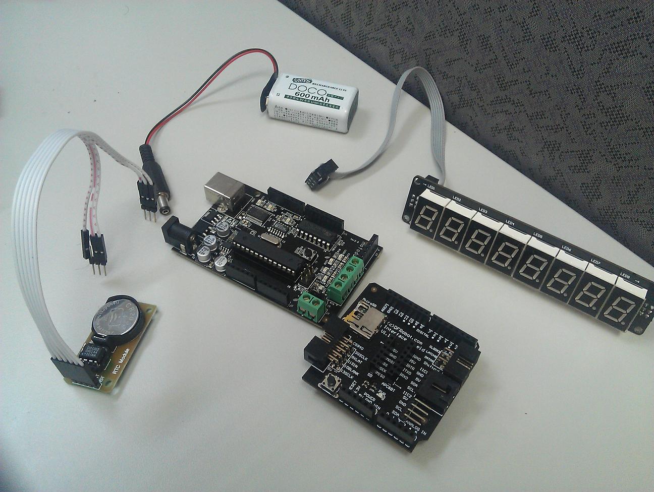
Clock = Arduino / Motoduino + RTC (DS1307) + SPI LED (7-Segment)

利用RTC module和LED七段顯示器做出一個簡單的時鐘, SPI介面可以省去許多arduino的IO pin.


DIY材料:
1.Arduino
2.RTC (DS1307) module
3.SPI LED module(7-segment)
4.Inteface Shield (option)
5.9V battery

Arduino sketch:

#include <stdio.h>
#include <string.h>
#include <DS1302.h>

//Pin connected to latch pin (ST_CP) of 74HC595
const int latchPin = 8;
//Pin connected to clock pin (SH_CP) of 74HC595
const int clockPin = 3;
////Pin connected to Data in (DS) of 74HC595
const int dataPin = 9;
byte Tab[]={0xc0,0xf9,0xa4,0xb0,0x99,0x92,0x82,0xf8,0x80,0x90,0xff};
byte Dot = 0x7f;
boolean DotOn;
/* Set the appropriate digital I/O pin connections */
uint8_t CE_PIN   = 5;  //RST
uint8_t IO_PIN   = 6;
uint8_t SCLK_PIN = 7;

/* Create buffers */
char buf[50];
char day[10];

/* Create a DS1302 object */
DS1302 rtc(CE_PIN, IO_PIN, SCLK_PIN);

void clearAll()
{
  for(int i=0; i<8; i++)
  {
    digitalWrite(latchPin, LOW);
    shiftOut(dataPin, clockPin, MSBFIRST, 0xff);
    digitalWrite(latchPin, HIGH);
    delay(10);
  }
}

void displayTime(byte h1, byte h2, byte m1, byte m2, byte s1, byte s2)
{
  if (DotOn)
  {
  digitalWrite(latchPin, LOW);
  // shift the bits out:
  shiftOut(dataPin, clockPin, MSBFIRST, s2);
  shiftOut(dataPin, clockPin, MSBFIRST, s1);
  shiftOut(dataPin, clockPin, MSBFIRST, Dot);
  shiftOut(dataPin, clockPin, MSBFIRST, m2);
  shiftOut(dataPin, clockPin, MSBFIRST, m1);
  shiftOut(dataPin, clockPin, MSBFIRST, Dot);
  shiftOut(dataPin, clockPin, MSBFIRST, h2);
  shiftOut(dataPin, clockPin, MSBFIRST, h1);
    // turn on the output so the LEDs can light up:
  digitalWrite(latchPin, HIGH);
  DotOn = false;
  }
  else
  {
  digitalWrite(latchPin, LOW);
  // shift the bits out:
  shiftOut(dataPin, clockPin, MSBFIRST, s2);
  shiftOut(dataPin, clockPin, MSBFIRST, s1);
  shiftOut(dataPin, clockPin, MSBFIRST, 0xff);
  shiftOut(dataPin, clockPin, MSBFIRST, m2);
  shiftOut(dataPin, clockPin, MSBFIRST, m1);
  shiftOut(dataPin, clockPin, MSBFIRST, 0xff);
  shiftOut(dataPin, clockPin, MSBFIRST, h2);
  shiftOut(dataPin, clockPin, MSBFIRST, h1);
    // turn on the output so the LEDs can light up:
  digitalWrite(latchPin, HIGH);
   DotOn = true;
  }
}

void print_time()
{
  /* Get the current time and date from the chip */
  Time t = rtc.time();

  /* Name the day of the week */
  memset(day, 0, sizeof(day));  /* clear day buffer */
  int Hour1 = t.hr/10;
  int Hour2 = t.hr%10;
  int min1 = t.min/10;
  int min2 = t.min%10;
  int sec1 = t.sec/10;
  int sec2 = t.sec%10;
 
  byte   h1 = Tab[Hour1];
  byte   h2 = Tab[Hour2];
  byte   m1 = Tab[min1];
  byte   m2 = Tab[min2];
  byte   s1 = Tab[sec1];
  byte   s2 = Tab[sec2];

    displayTime(h1, h2, m1, m2, s1, s2);
}


void setup()
{
  Serial.begin(57600);
  //set pins to output because they are addressed in the main loop
  pinMode(latchPin, OUTPUT);
  pinMode(dataPin, OUTPUT);
  pinMode(clockPin, OUTPUT);

  rtc.write_protect(false);
  rtc.halt(false);

  /* Make a new time object to set the date and time */
  Time t(2012, 7, 11, 21, 16, 37, 3);

  /* Set the time and date on the chip */
  rtc.time(t);
    clearAll();
}


/* Loop and print the time every second */
void loop()
{
  print_time();
  delay(1000);
}


Video: http://www.youtube.com/watch?v=RAb9WjOctdU

My Blog:  http://sinocgtchen.blogspot.com
More videos: http://www.youtube.com/user/sinocgtchen
Motoduino information: http://motoduino.com
My Email: sinocgtchen@gmail.com