總網頁瀏覽量

2015年10月21日 星期三

LED Web Controls by Intel Edison with I2C LCD1602


I2C devices 加到Intel Edison 其實很簡單,做法與arduino相同, 接上I2C device到 Edison Arduino後(藉由 S4A IO Board容易連接,請接到A4A5 位置),可以試著檢查系統是不是有偵測到裝置,command如 " i2cdetect -y -r 6 " , 直此命令後可以看到裝置的 I2C address. 注意的是Intel Edison 的 I2C bus是在 bus 6(Different to Raspberry Pi).

此實驗LCD顯示 Edison IP address, 然後User透過WIFI在瀏覽器上控制LED ON/OFF.

使用材料(Materials):
1. Intel Edison + Arduino Breakout Kit
2. S4A IO Board
3. I2C LCD1602
4. LED Terminal

首先, 把所有東西都接上去, 如下圖 , LCD1602接到 IO Board的 A4A5 位置, LED Terminal接到 D2D3 孔位.


1. 進入 Edison board system, 然後輸入 如下圖.
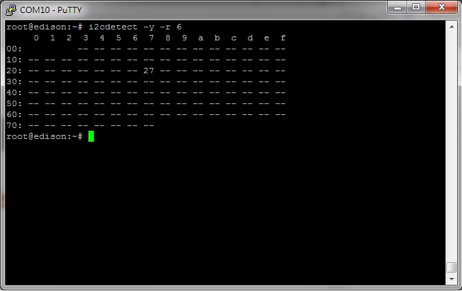

  LCD1602的 I2C address is 0x27

2. Open Arduino IDE,  copy the below sketch and paste it to Arduino IDE.

 #include <SPI.h>
#include <WiFi.h>
#include <Wire.h>
#include <LiquidCrystal_I2C.h>

char ssid[] = "xxxxxxx";      //  your network SSID (name)
char pass[] = "xxxxxxx";         // your network password
int keyIndex = 0;                 // your network key Index number (needed only for WEP)
LiquidCrystal_I2C lcd(0x27,16,2);  // set the LCD address to 0x27 for a 16 chars and 2 line display

int status = WL_IDLE_STATUS;
WiFiServer server(8080);

void setup() {
  Serial.begin(9600);      // initialize serial communication
  pinMode(2, OUTPUT);      // set the LED pin mode

  lcd.init();                      // initialize the lcd
  // Print a message to the LCD.
  lcd.backlight();

  lcd.print("Connecting...");

  // check for the presence of the shield:
  if (WiFi.status() == WL_NO_SHIELD) {
    Serial.println("WiFi shield not present");
    while(true);        // don't continue
  }

  String fv = WiFi.firmwareVersion();
  if( fv != "1.1.0" )
    Serial.println("Please upgrade the firmware");

  // attempt to connect to Wifi network:
  while ( status != WL_CONNECTED) {
    Serial.print("Attempting to connect to Network named: ");
    Serial.println(ssid);                   // print the network name (SSID);

    // Connect to WPA/WPA2 network. Change this line if using open or WEP network:  
    status = WiFi.begin(ssid, pass);
    // wait 10 seconds for connection:
    delay(10000);
  }
  server.begin();                           // start the web server on port 80
  printWifiStatus();                        // you're connected now, so print out the status
}


void loop() {
  WiFiClient client = server.available();   // listen for incoming clients

  if (client) {                             // if you get a client,
    Serial.println("new client");           // print a message out the serial port
    String currentLine = "";                // make a String to hold incoming data from the client
    while (client.connected()) {            // loop while the client's connected
      if (client.available()) {             // if there's bytes to read from the client,
        char c = client.read();             // read a byte, then
        Serial.write(c);                    // print it out the serial monitor
        if (c == '\n') {                    // if the byte is a newline character

          // if the current line is blank, you got two newline characters in a row.
          // that's the end of the client HTTP request, so send a response:
          if (currentLine.length() == 0) {
            // HTTP headers always start with a response code (e.g. HTTP/1.1 200 OK)
            // and a content-type so the client knows what's coming, then a blank line:  
            client.println("HTTP/1.1 200 OK");
            client.println("Content-type:text/html");
            client.println();

            // the content of the HTTP response follows the header:
            client.print("Click <a href=\"/H\">here</a> turn the LED on pin 9 on<br>");
            client.print("Click <a href=\"/L\">here</a> turn the LED on pin 9 off<br>");

            // The HTTP response ends with another blank line:
            client.println();
            // break out of the while loop:
            break;      
          }
          else {      // if you got a newline, then clear currentLine:
            currentLine = "";
          }
        }  
        else if (c != '\r') {    // if you got anything else but a carriage return character,
          currentLine += c;      // add it to the end of the currentLine
        }

        // Check to see if the client request was "GET /H" or "GET /L":
        if (currentLine.endsWith("GET /H")) {
          digitalWrite(2, HIGH);               // GET /H turns the LED on
          Serial.println("LED ON");
        }
        if (currentLine.endsWith("GET /L")) {
          digitalWrite(2, LOW);                // GET /L turns the LED off
          Serial.println("LED OFF");

        }
      }
    }
    // close the connection:
    client.stop();
    Serial.println("client disonnected");
  }
}

void printWifiStatus() {
  // print the SSID of the network you're attached to:
  Serial.print("SSID: ");
  Serial.println(WiFi.SSID());

  // print your WiFi shield's IP address:
  IPAddress ip = WiFi.localIP();
  Serial.print("IP Address: ");
  Serial.println(ip);

  // print the received signal strength:
  long rssi = WiFi.RSSI();
  Serial.print("signal strength (RSSI):");
  Serial.print(rssi);
  Serial.println(" dBm");
  // print where to go in a browser:
  Serial.print("To see this page in action, open a browser to http://");
  Serial.println(ip);

  lcd.clear();
  lcd.print(ip);

}

然後自行修改 ssid 和 pass 參數符合自己的 Router. (請自行下載 LiquidCrystal_I2C library)

3. Upload sketch to Edison. 等幾十秒鐘LCD會顯示 IP address.
4. 開啟PC瀏覽器輸入IP address and port 8080, 例如  http://192.168.1.28:8080

   請參考影片!

       https://youtu.be/vfpTnySBfiw


2015年3月25日 星期三

利用 Motoduino 修改 HC-06 藍牙模組名稱 (Change bluetooth 2.0 name)


通常在市面上買來的HC-06藍牙模組 名稱大都是 linvor 或 HC-05, 這次來說明利用motoduino來修改模組名稱(其實跟修改baud rate方法一樣,只是AT Command不同)

在 Motoduino上修改藍芽模組Baud Rate很簡單 步驟如下:

範例說明是以藍牙HC-06傳輸速率Baud Rate為 57600 bps例子

1.打開 Arduino IDE 輸入底下程式(下圗)

2.把Motoduino接上PC

3.Compile程式然後upload到板子.

4.等upload完後,移開motoduino跟PC連線,插上藍芽模組(如下圗).


5. 把Motoduino再接上PC, 然後開啟Arduino的Serial Monitor如下圖注意右下角的baud rate欄位選成57600bps,  Serial Monitor內會顯示AT+NAMEMotoduinoOKsetname (如下圗), 此時藍芽模組名稱已改成Motoduino.

6. 可以用android手機連線試試!


ps. 修改藍牙模組 baud rate 請參考這裡 


2014年11月16日 星期日

Arduino NFC/RFID = Arduino UNO + NFC Reader (PN532)


NFC/RFID 實驗在Arduino 上其實也很簡單, 這次利用PN532相容板來做實驗, 此塊板子支援 I2C 和 SPI介面, 我就來用 SPI 跟Arduino連接! 參考下圖:

Arduino       PN532
    D10  ------>  SS
    D11  ------>  MOSI
    D12  ------>  MISO
    D13  ------>  SCK
     5V  ------->  5V
    GND ------>  GND


Sketch 範例程式:

 #include <arduino.h>
#include <PN532.h>

#define SCK 13
#define MOSI 11
#define SS 10
#define MISO 12

PN532 nfc(SCK, MISO, MOSI, SS);

void setup(void) {
    Serial.begin(9600);
    Serial.println("Hello!");

    nfc.begin();

    uint32_t versiondata = nfc.getFirmwareVersion();
    if (! versiondata) {
        Serial.print("Didn't find PN53x board");
        while (1); // halt
    }
    // Got ok data, print it out!
    Serial.print("Found chip PN5"); Serial.println((versiondata>>24) & 0xFF, HEX);
    Serial.print("Firmware ver. "); Serial.print((versiondata>>16) & 0xFF, DEC);
    Serial.print('.'); Serial.println((versiondata>>8) & 0xFF, DEC);
    Serial.print("Supports "); Serial.println(versiondata & 0xFF, HEX);

    // configure board to read RFID tags and cards
    nfc.SAMConfig();
}


void loop(void) {
    uint32_t id;
    // look for MiFare type cards
    id = nfc.readPassiveTargetID(PN532_MIFARE_ISO14443A);

    if (id != 0) {
        Serial.print("Read card #"); Serial.println(id);
    }
}


PN532 arduino library 下載點 here.

很簡單! 拿起 NFC tag 感應一下就會跑出 Card id.


2014年10月28日 星期二

傳統伺服馬達(Servo) 改造成 可回饋位置伺服馬達(Smart Servo) Servo Hacked!


幾個月前買了幾顆二手伺服馬達  HITEC HS-311, 今天就來Hacked成可以角度回饋伺服馬達!
市售HS-311 也有新舊版之分(難道是山寨之分?)如下圖.
           

外殼拆開後可以看出電路板走線及IC也不一樣(如下圖), 不過沒關係這種類比伺服馬達原理都一樣利用VR Encoder(可變電阻)來回授位置!


只要找到Encoder回授信號(電壓值)位置,焊條電線連接出來即可以取的馬達轉動位置電壓值,
利用此電壓值可以換算馬達目前處於哪個角度位置, 焊接位置請參考下圖!


焊接線完後整理外殼出線位置,讓回饋電線容易拉出及蓋上外殼,如下圖!


接下來開始寫程式量測回饋訊號電壓及算出角度,Arduino參考程式如下,程式不難容易理解,
把回饋線路接到Arduino A0位置, 主要針對角度 0, 45, 90, 135, 和 180度取得回饋電壓值!


#include <Servo.h>

//servo object
Servo myservo;

//servo position
int pos = 0;
//positions (in degrees) to send to the servo
int positions[] = {0, 45, 90, 135, 180};
int numPositions = 5;

int numMeasurements = 1;
//increase this value to read feedback multiple times and then calculate the arithmetic average

void setup()
{
  //control servo via pin 9
  myservo.attach(3, 650, 2350);
  //start serial comm. for debugging
  Serial.begin(9600);
}

void loop()
{
  int i = 0;
  //iterate over positions
  for(i = 0; i < numPositions; i++)
  {
    pos = positions[i];
    int j = 0;
    double sum = 0;
    double sensorValue = 0;
 
    Serial.print("SETTING:");
    Serial.println(pos);
    myservo.write(pos);
 
    //wait a bit, to give the servo time to reach the requested position
    delay(800);
 
    //read the feedback via A0, once or multiple times
    for(j = 0; j<numMeasurements; j++){
      sum += analogRead(A0);
    }
 
    //calculate average if numMeasurements > 1
    sensorValue = (sum/numMeasurements);
    Serial.print("READ:");
    Serial.println(sensorValue);
 
    //wait for three seconds
    delay(3000);
  }

}


如果調整修改好程式,基本上smart motor改造完成, 可以利用下面程式換算成角度,角度多少會有誤差幾度!

#include <Servo.h>
#include <math.h>

//servo object
Servo myservo;

//servo position
int pos = 0;
//positions (in degrees) to send to the servo
int positions[] = {0, 45, 90, 135, 180};
int numPositions = 5;

int numMeasurements = 5;

//HS-311 servo parameters
int zero_degrees = 98;  // HS-311 New version: 94; Old version: 98
double one_degree = 1.5111;//HS-311 New Version: 1.4889; Old version: 1.51111;

void setup()
{
  //control servo via pin 9
  myservo.attach(3, 650, 2350);
  //start serial comm. for debugging
  Serial.begin(9600);
}

void loop()
{
  int i = 0;
  //iterate over positions
  for(i = 0; i < numPositions; i++)
  {
    pos = positions[i];
    int j = 0;
    double sum = 0;
    double sensorValue = 0;
 
    Serial.println("SETTING:");
    Serial.println(pos);
    myservo.write(pos);
 
    //wait a bit, to give the servo time to reach the requested position
    delay(800);
 
    //read the feedback via A0, once or multiple times
    for(j = 0; j<numMeasurements; j++){
      sum += analogRead(A0);
    }
 
    //calculate average if numMeasurements > 1
    sensorValue = (sum/numMeasurements);
    Serial.println("READ:");
    Serial.println(calcH311ServoPosition(sensorValue));
 
    //wait for three seconds
    delay(3000);
  }

}

double calcH311ServoPosition(double val){
  val -= zero_degrees;
  val /= one_degree;
  val = floor(val);

  return val;
}


這樣就可以DIY製作出一顆可回授位置的伺服馬達!!


2014年10月7日 星期二

Kozig LED I2C介面的七段顯示器: 修改I2C Address

使用I2C 介面的七段顯示器顯示數字最方便不過了! 此款I2C LED Display 便宜又好用,這次來說明如何修改 I2C Address, 通常買來Address為 0x27.


步驟如下:

1.斷電情況下將SCL接到GND, SDA接A4.
2.接通電源,顯示 -51- 時,表示進入設定新地址模式.
3.再將原來SCL接GND改接到A5.
4.執行 SEG8B4A036A_SetAddress, (ztlib example)結束時會顯示新位置.
    (下載I2C LED 的 Arduino Library)
5. 移除電源,LED 模組已改成新位址!


Motoduino 把此I2C LED連接使用簡單化, 可以利用RJ11 電話線接到 IO Board 的 A4,A5孔位即可使用.


2014年9月27日 星期六

Arduino I2C LCD 20x4 lines Display


這來試試 LCD 20x4 lines, 利用Arduino加上 IO Board 接線方便許多!
可顯示的字元比 常用LCD 16x2 lines 多許多!


步驟一: 下載 I2C LCD library, 解壓縮後放入Arduino Libraries內

步驟二:  撰寫程式如下:

#include <Wire.h>
#include <LiquidCrystal_I2C.h>

// set the LCD address to 0x20 for a 20 chars 4 line display

LiquidCrystal_I2C lcd(0x27, 2, 1, 0, 4, 5, 6, 7, 3, POSITIVE);  // Set the LCD I2C address
//假設 I2C address 0x27

void setup()   /*----( SETUP: RUNS ONCE )----*/
{
  Serial.begin(9600);  /

  lcd.begin(20,4);  
  for(int i = 0; i< 3; i++)
  {
    lcd.backlight();
    delay(250);
    lcd.noBacklight();
    delay(250);
  }
  lcd.backlight();

  lcd.setCursor(3,0); //Start at character 4 on line 0
  lcd.print("Motoduino Lab!");
  lcd.setCursor(2,1);
  lcd.print("www.motoduino.com");
  lcd.setCursor(0,2);
  lcd.print("20x4 LCD Display");
  lcd.setCursor(0,3);
  lcd.print("I2C Interface");

}/*--(end setup )---*/


void loop()
{

}


2014年9月25日 星期四

香蕉派 (Banana Pi) 搭配 MotoPiduino 使用 UART/Serial Console


最近拿到一塊 Banana Pi, 馬上就先拿來搭配MotoPiduino, 如果想要利用Serial Console 下命令, 則必須修改 debug 用的 UART Port. 在樹莓派 Raspberry Pi上 只有一個 UART0, 但是在Banana Pi上UART0是不在 26Pin GPIO上(對應Raspberry Pi GPIO)而是在 UART2, 所以就來把Debug UART0 改成 UART2位置,這樣就跟Raspberry 一樣debug UART位置GPIO 26pin.

步驟:

1.硬體接線請參考


二. 修改 inittab 檔案


三. 修改檔案 inittab 最後一行,  ttyS0 改成 ttyS2,  存檔後Banana Pi關機!


四. 接線換位置如下圖:


五. 重新啓動後初始化訊息還是會從UART0輸出,但是過二三十秒後, PC上的Serial Console (Putty 或 Serial Minitor軟體)會顯示 login 訊息, 此時輸入 bananapi,  password也是輸入bananapi, 就進入Console 模式.


http://www.motoduino.com