總網頁瀏覽量

2012年4月20日 星期五

Changes Bluetooth Baud Rate / Name on Motoduino/Arduino (AT Command)

這次來說明另一個簡單的方式修改bluetooth設定值,利用Arduino IDE直接下AT Command給bluetooth修改藍芽名稱或Baud Rate等, 此範例以藍芽名稱為例, 修改Baud Rate方法一樣,AT Command不一樣而已.

步驟如下:
1.把Motoduino/Arduino MCU 移除,如下圖:


2. 需要一條4 pin 或 6 pin排線把BT跟Motoduino做連接,注意Bluetooth的RX接Motoduino/Arduino的RX, Bluetooth的TX接Motoduino/Arduino的TX. Bluetooth的Vcc接 板子Vcc, GND接GND, 只需接四根pin腳.如下圖:


3. 把板子連接PC, 打開Arduino IDE 選擇正確的 Serial Port,如下圖:


4. 注意Arduino IDE的baud rate設定,如果Bluetooth目前default baud rate是 57600,則設定為57600,和No Line Ending. 如下圖:


5. 開始下AT Command給bluetooth, 下 AT 則會回應 OK, 在此以修改藍芽名稱為例, AT+NAMEMOTOBT , ( 如修改baud rate則 AT+BAUD7 表示設定baud rate成 57600)


 6. Bluetooth 回應的訊息, OKsetname表示藍芽名稱修改完成.
                                                   
7. 移除板子電源,把Atmega328P or MCU 插上板子還原. 這樣就大功告成!!


部落格 : http://sinocgtchen.blogspot.com
Motoduino資訊: http://motoduino.com


2012年4月18日 星期三

手機遙控智慧車 = Motoduino(Arduino + L293D) + two Servos (伺服馬達) + Bluetooth

把兩顆伺服馬達(兩個自由度,可以承受13kg大扭力)架設在小車子上,且把照相功能的攝影鏡頭架在伺服馬達上,利用Motoduino跟藍芽傳輸控制訊號,Android­手機可以控制鏡頭角度,目前照相功能未整合進去,不過測試是沒問題的,下一階段在整合進去...


DIY使用材料:
1. Motoduino (Arduino + L293D)
2. Bluetooth module
3. MG995 Servo  x 2
4. 9V battery
5. 兩輪小車一台
6. IO Expansion Shield (option, 可省略)
7. Android phone


                                        IO Expansion Shield
  
                                                          
                                         MG995 伺服馬達


    影片:  http://www.youtube.com/watch?v=Ass0XSu98wE


更多影片請看: http://www.youtube.com/user/sinocgtchen
部落格 : http://sinocgtchen.blogspot.com
Motoduino資訊: http://motoduino.com


2012年4月8日 星期日

Stepper Motor Control (步進馬達控制) = Motoduino (Arduino+293D) + Stepper Motor

Motoduino這塊板子也可以控制步進馬達(stepper motor), 方法很簡單, 手上這顆是二相激磁四線式步進馬達, 電壓 5V, 精度1.8度, 電流 0.3A, 四線接法: 紅線接M1+, 棕色接M1-, 藍色接 M2-, 黃色接 M2+. 影片中實驗是順時針走 200步(200x1.8度=360)剛好一圈,逆時針走200步回原點. 


 影片請參考這裡 : http://www.youtube.com/watch?v=AIZBQgjQ3rQ

使用材料:


1. Motoduino
2. Stepper Motor (KH42JM2B011) 5V, 0.3A, 1.8 Deg.


The Sketch(for Motoduino):


#include <Stepper.h>

const int stepsPerRevolution = 200;  // change this to fit the number of steps per revolution
                                     // for your motor
const int Motor_E1 = 5; // digital pin 5 of Arduino (PWM)  
const int Motor_E2 = 6;  // digital pin 6 of Arduino (PWM)
const int Motor_M1 = 7;     // digital pin 7 of Arduino
const int Motor_M2 = 8;    // digital pin 8 of Arduino
//Stepper myStepper(stepsPerRevolution, 8,9,10,11);          
Stepper myStepper(stepsPerRevolution, Motor_M1, Motor_M2);          

void setup() {
  // set the speed at 60 rpm:
  myStepper.setSpeed(60);
  // initialize the serial port:
  Serial.begin(9600);
  pinMode(Motor_M1, OUTPUT);
  pinMode(Motor_M2, OUTPUT);

  digitalWrite( Motor_E1, HIGH);  // speed control
  digitalWrite( Motor_E2, HIGH);  // speed control
}

void loop() {
  // step one revolution  in one direction:
   Serial.println("clockwise");
  myStepper.step(stepsPerRevolution);
  delay(500);

   // step one revolution in the other direction:
  Serial.println("counterclockwise");
  myStepper.step(-stepsPerRevolution);
  delay(500);
}


Blog: http://sinocgtchen.blogspot.com
Motoduino : http://motoduino.com
Youtube: http://www.youtube.com/user/sinocgtchen
My Email: sinocgtchen@gmail.com


2012年3月11日 星期日

Motoduino / Arduino WiFi Shield ( IEEE 802.11b 無線網路擴充板)

Motoduino WiFi Shield v1.0主要是配合Arduino (Diecimila/Duemilanove/Uno) 及 Motoduino 板子所設計,讓Arduino/Motoduino能有無線網路的功能且提供IEEE 802.11b連線能力。此塊模組完全相容於 Asynclab WiShield 1.0 和 Cupperhead WiFi Shield。


Motoduino WiFi模組特性(Microchip):
 802.11b Wi-Fi certified
 1Mbps and 2Mbps throughput speeds
 Supports both infrastructure (BSS) and ad hoc (IBSS) wireless networks
 Ability to create secured and unsecured networks
 WEP (64-bit and 128-bit)
 WPA/WPA2 (TKIP and AES) PSK
 Low power usage
 Sleep mode: 250μA
 Transmit: 230mA
 Receive: 85mA


腳位說明:
 1.SPI 介面
     * Slave select (SS) : Arduino pin 10 
     * Clock (SCK) : Arduino pin 13
     * Master in, slave out (MISO) : Arduino pin 12
     * Master out, slave in (MOSI) : Arduino pin 11
 2. Interrupt (Uses only one of the following, depending on jumper setting)
     * INT0 : Arduino pin 2 
     * DIG8 : Arduino pin 8 
 3. LED : Arduino pin 9 
     * To regain use of this pin, remove the LED jumper cap
 4. 5V power
 5. GND


實做應用參考網站:  http://www.youtube.com/user/sinocgtchen
 部落格參考網站 :   http://sinocgtchen.blogspot.com
 Motoduino相關資訊: http://motoduino.com


2012年3月6日 星期二

Remote Control LED Matrix = Android + Motoduino (Arduino) + MAX7219 + Bluetooth

最近做一個LED 8x8 實驗,主要是利用手機藍芽來控制一個8x8 LED,這個實驗不是很難,主要在硬體接線部分要搞清楚pin腳的對應.

使用材料:
1. LED 8x8 matrix
2. Bluetooth
3. Motoduino or Arduino
4. MAX7219
5. 27k 電阻
6. 10uF 電容
7. 0.1 uF 電容
8. 一些線材


線路圖請參考這裡(reference schematic): Arduino playground

手機程式下載處(download android apk): http://www.motoduino.com/tw/downloadfiles


  影片請看: http://www.youtube.com/user/sinocgtchen
   部落格 :  http://sinocgtchen.blogspot.com

   有任何問題或有興趣朋友,歡迎來信討論,謝謝!!


2012年2月19日 星期日

手機藍芽遙控車DIY = Motoduino (Arduino + L293D) + Toy Car + Bluetoorh + Android Phone

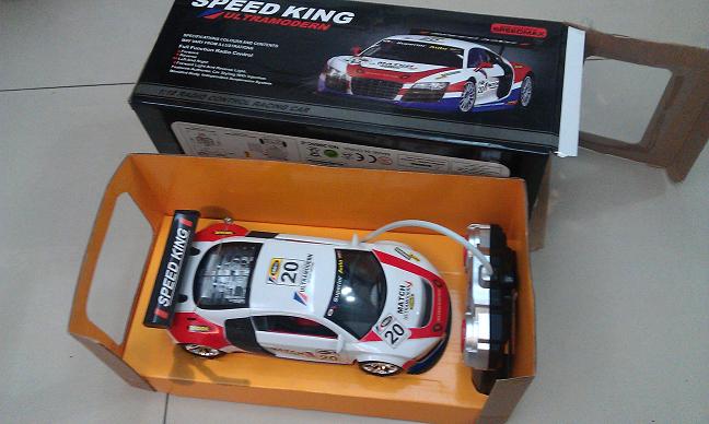
這次新年去夜市買一台傳統RF遙控玩具車(NT$199)給兒子玩,他玩得非常開心,過完年他已經玩膩了,就找個時間把它改裝成Android手機遙控車.其實搭配Motoduino是非常簡單實現.有興趣想製作的朋友可以按照底下說明來製作.

材料:
1. Motoduino (Arduino + L293D) 一片

2. 9V 電池扣含 DC JACK電源接頭 一條
3. 藍芽模組 一片
     
4. RF玩具遙控車( 兩顆DC馬達) 一台 (不要小於1:18車型)
 
                 
5. 電池: 9V 一顆, 3號電池四顆
6. 單芯線幾條(紅/黑)
7. 雙面貼紙 一小片(固定Motoduino板子)

步驟如下:
1. 先下載/燒入sportcar.ino sketch到Motoduino上,來不及放在網站下載,請來信索取.
2. 首先用螺絲起子從車底拆開玩具車,車內的座椅都移除,才有空間放板子.
3.移除裡面的電路板及天線
4.把電池盒的電源線焊接到Motoduino的DC JACK處,(紅線是正極,黑線是負極) ,不可接錯!
   如下圖.
 
 5. 把前輪馬達正負極接到Motoduino的M2+及M2-, 後輪馬達正負極接到M1+及M1-,如下圖.
   
 6.把板子用雙面膠固定在車體上,或螺絲固定上去.
 7.此款玩具車前後都有LED燈共四顆,前進時頭燈亮,後退時後燈亮,線路如下圖,目前我先暫時接  到motoduino pin 10跟pin 11(紅線),黑線接地(GND),未來可以控制車燈,留給有興趣者去修改.


  8. 外接馬達電源,把9V電源接到Motoduino Ext. Vin的地方,正負極不能搞錯, J5(Jumper 5)要跳到Ext. Vin,表示馬達獨立供電(由9V電池堤供),如下圖
   
  9. 把車頂外殼想辦法割一個洞好讓Bluetooth插上去Motoduino.
   
   10. 把車子組裝起來, 外殼蓋上去車子底盤,螺絲鎖緊!
         
  11.接上電池及藍芽模組, 此範例是把9V電池外移到車子外面,如沒電時容易替換.
   

  12. 請在此(http://www.motoduino.com/download )下載Android 手機遙控車程式 (MduinoBT2.apk),且安裝到手機上.
 
   13.開起車子電源開關, 用手機搜尋藍芽裝置.
   14.開始遙控去.................

   影片請看: http://www.youtube.com/watch?v=Y-PPmnypRWg
   製作過程請參考部落格 : http://sinocgtchen.blogspot.com
   Motoduino資訊: http://motoduino.com


2012年1月7日 星期六

手機遙控履帶坦克車= Motoduino ( Arduino ) + Bluetooth 藍芽 + Android

把擺一段時間履帶坦克車(田宮系列TAMIYA模型玩具)拿出來修改一下,這次用 motoduino板子來組裝就簡單許多. G-Sonsor手機遙控整體上還不錯!

使用的材料:
1. Motoduino + bluetooth (購買資訊)
2. 電池 9V
3. 三號電池 1.5V x 4
4. 田宮系列 TRACK&WHEEL SET 履帶組 (露天拍賣可買到, 如下圖)
5. 田宮系列 雙馬達4速變速箱 TWIN MOTOR GEAR BOX (露天拍賣可買到, 如下圖)
6. 田宮系列 Universal Plate  (露天拍賣可買到, 如下圖)


Youtube video: http://www.youtube.com/user/sinocgtchen 


  影片請看: http://www.youtube.com/user/sinocgtchen
   部落格 : http://sinocgtchen.blogspot.com
   Motoduino資訊: http://motoduino.com

My Email: sinocgtchen@gmail.com